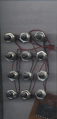
- Procdure
- Develop Schematic of base electonics
- I did only a rough version of this since I need very few of the components on the board I used. Many of the capicators and connections are for a pulse of the LEDs when the computer is started and connections to the keymatrix I didn't need. This also included tracing the keymatrix the keyboard used befor modification.
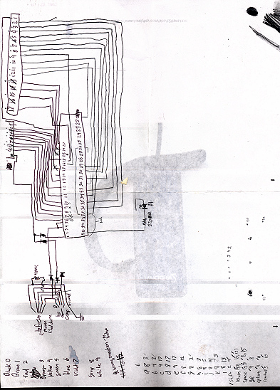
- Prepare board artwork
- After finding the correct connection I needed I set out to make a smaller board for my project. The main part needed was a 40-pin IC and took up most of the room needed. The rest of the board was traces for the other small parts and wires leeding to the switchs needed to reporduce the effect caused by the keybaord membrane.
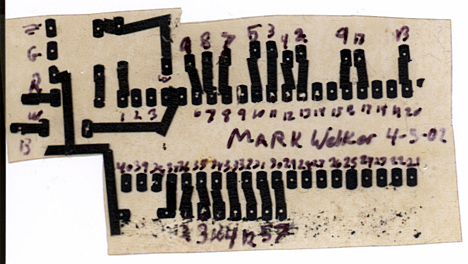
- Develop board
- First I had to expose a positive version of my board artwork to a positive type copper board using UV light I then stoped the processing with positive type developer which also reveled my imageby removing unwanted covering. The final step was to put the board into etching solution untill all excess copper was removed. The after checking my copper traces I drilled holes for my various components.
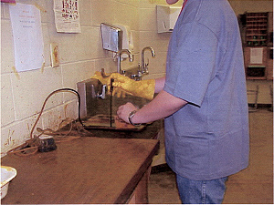

- Tranfering Parts
- After finishing my board I started desoldering parts from the old board to allow me to transfer parts to the new one. I did this with a soldering iron and copper braid. After doing the 40 pins on the IC I needed I also did the diodes I needed and the ADB port on the keyboard.
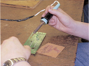
- Soldering Parts
- After removing and transfering parts from the old board I made sure they were placed correctly and soldered the tabs to my board. During the time I used I als checked to make sure there were no solder bridges that could cause problems.
- Key Matrix
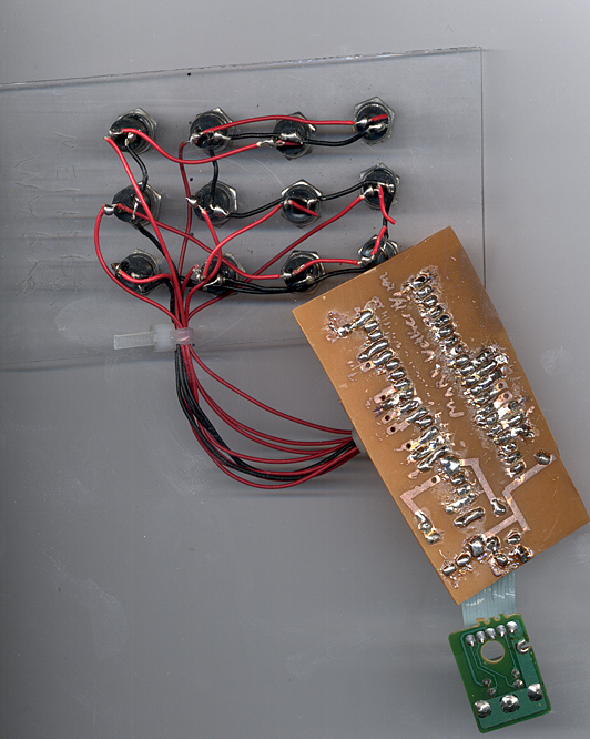
- The Key Matrix is the key part of the project, since it would be the part I would use to input information into the computer. Since I was basing my project on a QWERTY keyboard I traced pins for the letters A-L so I would not have to remap them when I finshed the hardware. I mad the key matrix by useing a 26 gauge insulated wire that I could string tough the holes in the switch solder tabs. Using an exacto knife I stripped the insulation where nesicary. By being careful where the exposed wire was I could go ahead and string the wire though the tabs
- Casing
- Even before finishing the wireing I had cut a frount panel for my project to help keep the buttons in place so once I was finshed with the two sectinos of buttons I could easily cut and assemble the project. The only major problem to arrise here was the different angles the case needed, though this was solved by making angle brackets out of an EM shield from an old computer case. After making the angle brackets I drilled holes for the machine screws I used to pass though to the metal. I then attached a nut to most of the machine screws (in some cases the metal brackets act as a nut on thier own) After assembling it.
